- Home
- About
- Products
- SHOP
- Markets
- Applications
- Support
- Contact Us
- Latest News
ATEX Instruction Manual 📰
14th Jul 2020ATEX IECEx Load Cells
Introduction
This manual refers to LCM Systems range of ATEX and IECEx certificated load cells and enclosures. This and any reference documents should be read and understood before installing or operating any LCM systems ATEX, IECEx products. All LCM Systems ATEX, IECEx load cells will be accompanied by a general arrangement drawing or datasheet, calibration certificate, declaration of conformity and a copy of LCM systems ATEX, IECEx certificates as a minimum. All LCM Systems ATEX IECEx enclosures will be accompanied with the same documentation as stated above for load cells minus a calibration certificate.
All LCM Systems ATEX, IECEx products are design and manufactured in accordance with Directive 2014/34/EU and the following standards: IEC 60079-0:2011, IEC 60079-1:2014 and IEC 60079-31:2013, BS EN 60079-0:2012, BS EN 60079-1:2014 and BS EN 60079-31:2014.
Product Description
Item: Load Cell or Enclosure Group II, Category 2, Zone 1 Environment
Model Numbers: ACP (compression load cell), AEN (enclosure), ALL (load link), ALP (load pin) SHK-A (load shackle) and LCMXXXX (custom design).
All LCM Systems load cell designs are allocated a unique LCM number/model number i.e. LCM Number = LCMXXXX (where X=0-9 i.e. LCM4204) or model number (i.e. ACP-2-ATEX). LCM Systems send a drawing to the customer for approval prior to the manufacture of any custom designed hazardous area load cell.
Supplier: LCM Systems Ltd - Unit 15, Newport Business Park, Barry Way, Newport, Isle of Wight PO30 5GY UNITED KINGDOM
Service: (REPAIR, SUPPORT)
LCM Systems Ltd - (Address as above)
Tel: +44(0)1983 249264
Fax: +44(0)1983 249266
E-mail: sales@lcmsystems.com
Markings:
The Label will be affixed to the Load cell or enclosure as shown in the general arrangement drawing supplied. The label will be as to drawing LCM4255/9, information on the label is shown as follows:-
Load Cells
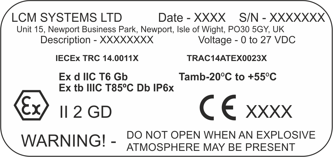
The Following Certification Numbers cover Models: - Load Pin 4255, Link Load Cell 4256, CPA Load Cell 4257.
TRAC14ATEX0023X and IECEx TRC 14.0011X
Enclosure
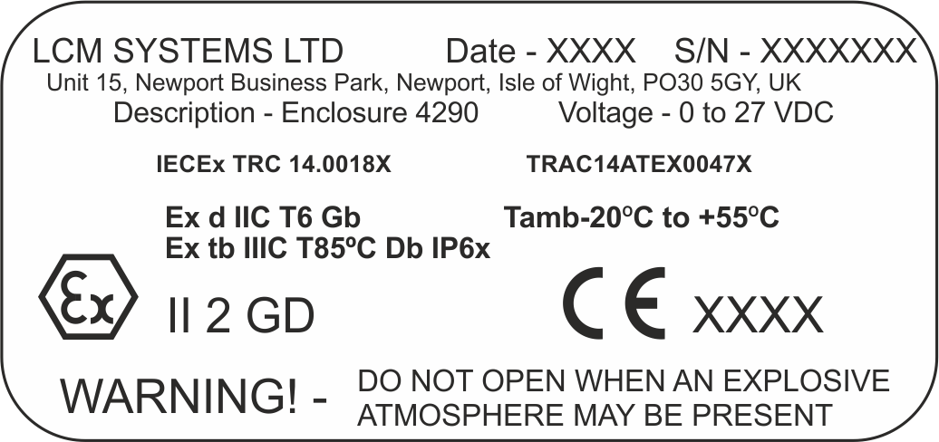
The Following Certification Numbers cover Models: - Enclosure 4290.
TRAC14ATEX0047X and IECEx TRC 14.0018X
Installation
All LCM Systems ATEX/IECEx certificated products should be installed as shown on the supplied general arrangement drawing. Load direction will be marked on each load cell and clearly shown on the drawing. All cable entry/exit points are clearly labelled with the thread type and size on the load cell or enclosure and the drawing. All wiring or connector pin details are shown on the calibration certificate and where applicable on the load cell or enclosure drawing. All earthing points must have a cross sectional area at least equal to the cross sectional area of the phase conductor.
LCM Systems do not supply any detailed installation instructions for their equipment due to the equipment being designed as to customer details or the equipment is for portable usage.
If LCM System equipment is supplied with additional Ex hazardous area products (displays etc.) it is not the responsibility of LCM Systems to verify suitability or provide additional installation details for these products. All additional equipment not covered by LCM systems certification must be installed in accordance with the latest issues and relevant parts of EN60079 specifications or the equivalent IEC specification - Sections. Installation and maintenance of electrical apparatus for use in potentially explosive atmospheres (other than mining applications or explosive processing and manufacture) must be in accordance with:
EN60079-14:2014 Electrical installation in hazardous areas (other than mines)
IEC60079-14:2013
BS EN 60079-10-1:2015 Classification of Hazardous Areas
BS EN 60079-10-2:2015
IEC 60079-10-1:2015
IEC 60079-10-2:2015
Manufacture
LCM Systems carries out the design and manufacture of ATEX, IECEx load cells and performs full testing and inspection of each item in accordance with IEC 80079-34 QMS system.
Repairs
Only LCM Systems personnel are authorised to carry out a repair or service to their products. All repairs or services will be carried out in the premises of LCM Systems, the unit is not serviceable out of LCM Systems premises.
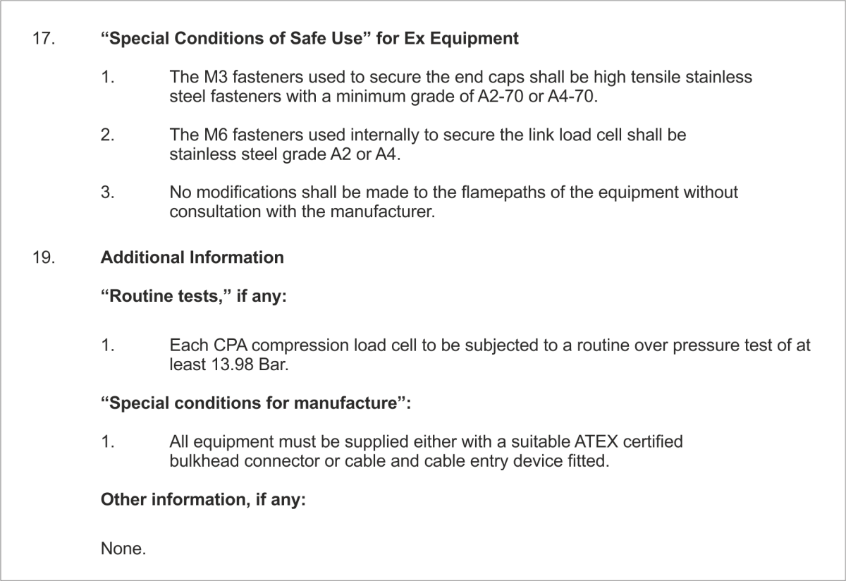
Assembling and Dismantling
Assembling and dismantling of load cells will be carried out by LCM System Ltd Personnel only. Third party attempts will render the certification for the unit invalid. Enclosures can be assembled and dismantled by third party engineers outside of a hazardous area only. All seals and fixings must be fitted correctly in accordance with the general arrangement drawing.
Emergency repairs
Emergency repairs will involve returning the unit to LCM Systems Ltd premises for servicing and prompt return to the customer, should the item be deemed suitable for return.
Adjustments
Adjustments for Parameter/Calibration to the Unit: For Calibrating the unit, it is recommended that this is carried out by a member of LCM Systems or a fully competent Instrument Engineer.
No Internal adjustments are required or permitted.
Any other Interference will render the unit invalid as a certified product and require it to be returned to LCM Systems for analysis and/or re-adjustment.
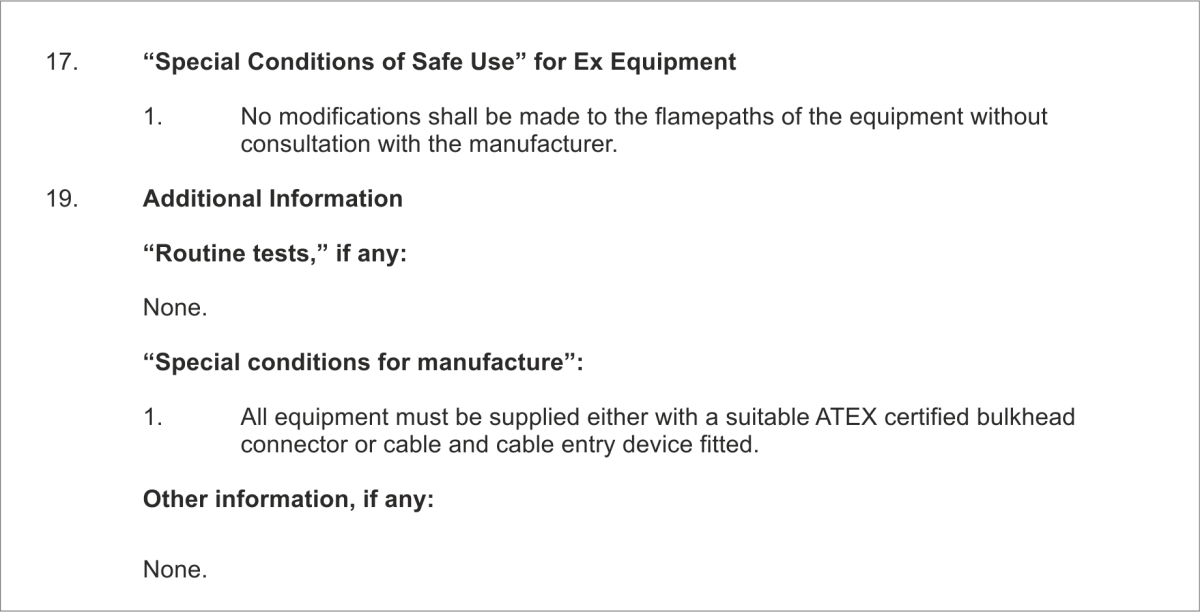
WARNING The load cell or enclosure should NEVER be opened when an explosive atmosphere may be present. Any repairs or adjustments must only ever be carried out in a Non-explosive environment.
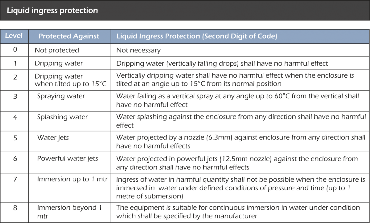
The user should determine media effects on the exposed transducer materials. Where a corrosive environment is present transducers can often be manufactured from corrosion resistant materials or alternatively, isolation barriers can be employed between the corrosive environment and the transducer. The Ingress protection rating (IP) should never be exceeded see table A & B below for details
ALL details shown on the general arrangement drawing and ATEX, IECEx certificate should never be exceeded for any LCM Systems products.
Table A: - Solid particle protection
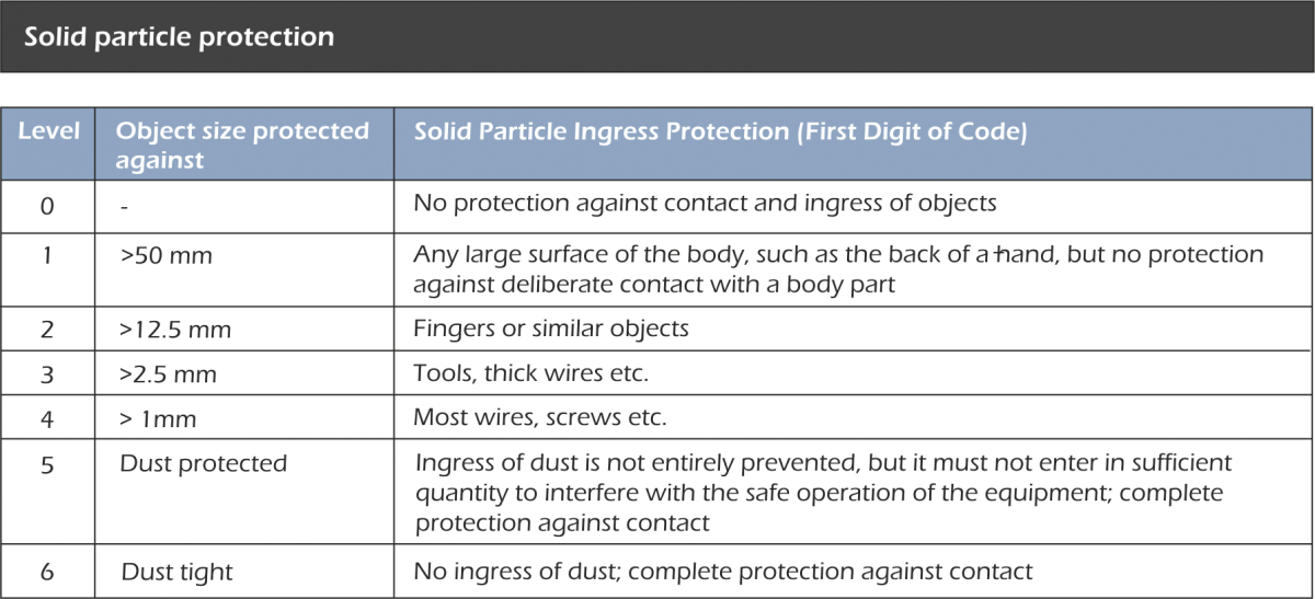
Table B: - Liquid ingress protection